Introduction to Torque
The measure of a force's tendency to produce a rotation about an axis is called torque. That is, if a force is used to begin to spin something, or to attempt to spin something, a torque is generated. A torque would also be generated if a force was used to stop something from spinning.
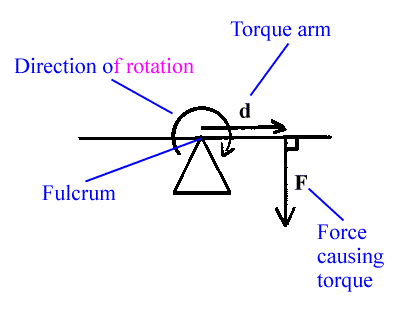
For example consider a stick or board that is placed horizontally and is attached to an axis at its center so that it can rotate. This would be somewhat like a seesaw or teeter-totter. If a force pulled down on the right side of this board, then it would rotate clockwise. All of this, along with some other terms, is symbolized in the following diagram:

-
The horizontal stick or board is drawn as the obvious horizontal line. For our purposes here, consider the board to have no mass. In situations like this this board is called a lever.
-
The triangle is thought of as a type of support for the board allowing the board to rotate at its tip. This point of rotation is called the fulcrum, or axis.
-
A force is drawn on the right side of the board, shown as a vector labeled F. Think of this as a force acting on the board and in a direction perpendicular to the board, pulling it downward at this moment.
-
The direction of rotation caused by this force is shown with a curved arrow. This is a clockwise rotation.
-
The distance from the point of rotation, or fulcrum, to the point on the board where the force is applied is called the torque arm. Above it is shown as a vector pointing to the right and labeled d.
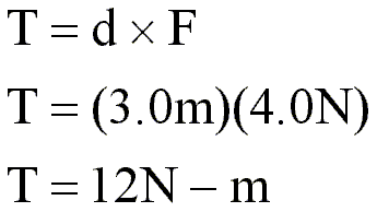
We say that the above force causes a clockwise torque to be placed on the board. This torque is calculated by multiplying the length of the torque arm times the size of the force. If the torque arm was 3.0 meters long and the size of the force was 4.0 Newtons, then the calculation for the torque would look like this:

This calculation would be interpreted in the following way:
-
The first line would be read 'Torque equals the length of the torque arm times the force causing the torque.' The symbol for torque is T, the symbol for the length of the torque arm is d, and the symbol for the force is F. All three of these quantities are vectors.
-
The second line shows the values for the torque arm length and the force as they should be entered into the equation.
-
The last line presents the final numerical result for the torque, 12 N-m. The unit for torque is 'N-m'. This is pronounced 'Newton meter'. The dash in the unit is not pronounced.
This torque has a direction, since it is a vector. The direction which the above board will rotate is clockwise, so, the torque could be said to have a clockwise direction. This could be written as:
T = 12 N-m CW
However, torques that are clockwise are said to be directed 'into the page', or, if you are looking at a computer monitor, 'into the screen'. That is, in diagrams like the one above the torque vector is NOT to be imagined pointing to the left or right or up or down. Rather, torques point into the page, or out of the page. In the case of a clockwise torque, the vector points into the page; a counter-clockwise torque points out of the page.
Notice that the torque vector always points in a direction perpendicular to the plane defined by the torque arm vector and the force vector.
Now for some fine points:
-
Actually, this multiplication of the torque arm vector times the force vector is called a cross product. It should be read 'dcross F'. The cross product is a method of multiplying two vectors which generates another vector as its result. If the two vectors are perpendicular to each other, as they are in our above simple example, then the cross product proceeds as an ordinary multiplication. The cross product of two vectors becomes slightly more complicated if the two vectors are not perpendicular. We will cover more about cross products in the later examples regarding torque.
-
The direction of the torque, that is, whether it points into or out of the page, is actually governed by a rule called 'the right hand rule'. We will cover this in later examples, also. For now, understand that in examples as those above clockwise rotations are tied to torques pointing into the page, and counter-clockwise rotations are tied to torques pointing out of the page. Just think of how a common screw works. If you are looking at its head from above with it pointing away from you, then if it spins clockwise, or 'righty', it will move downward, or into the page. If it spins counter-clockwise, or 'lefty', it will move upward, or out of the page.