X- and Y-Components of a Force Vector
This article discusses the x- and y-components of a force vector. Understand that the diagrams and mathematics here could be applied to any type of vector such as a displacement, velocity, or acceleration vector.
For an understanding of vectors see the Vectors section of the Physics Department.
For an understanding of right triangle trigonometry see the Trigonometry and Right Triangles section of the Trigonometry Realms.
When you are finished with the material here, be sure to visit the Force Component Machine. It will show you how the positive and negative signs for the force components work for any direction that the two dimensional force vector may be pointing.
The two dimensional force vector
A force vector can be expressed in two dimensions on the (x, y) plane. For example, imagine the surface of a table top to be an (x, y) plane. Objects can be pushed across this table surface in several different directions, not just parallel to the length or width of the table. Objects can be pushed across a table top at a slanted direction relative to the edges of the table top. In the animation below we see several different directions in which you could push an object across a table top, or the several directions one can apply a force to an object on an (x, y) plane. The object being pushed is the green disk, and the force vector is the black arrow:
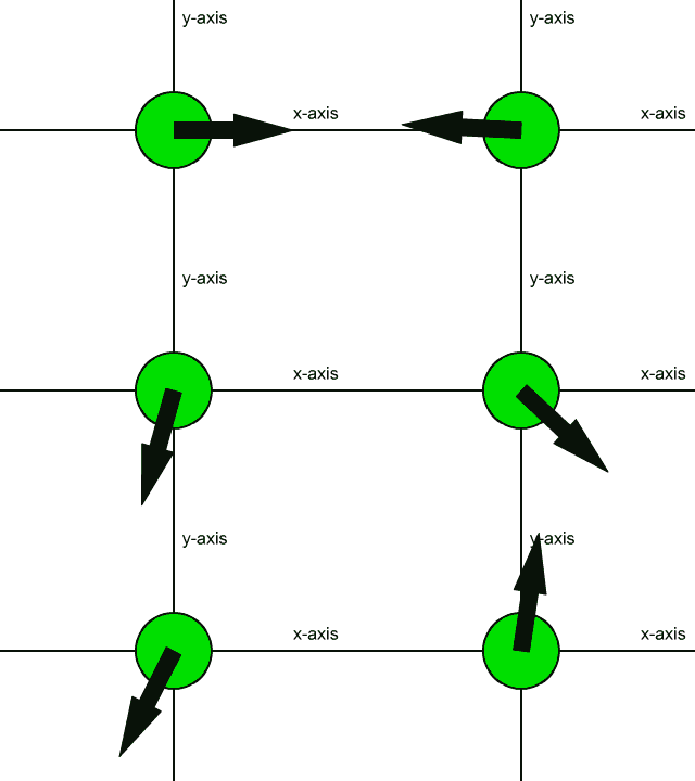
Force vectors like the one shown above are said to be two dimensional force vectors. You can think of them as forces that have a part that pushes right or left, and that have another part that pushes up or down. These parts of the force are called the components of the force. The component that pushes right or left is called the x-component, and the part that pushes up or down is called the y-component.
Force components and shadows
Mathematically, the components act like shadows of the force vector on the coordinate axes.
In the picture directly below we see a force vector on the (x, y) plane. The force vector is white, the x-axis is red, the y-axis is green, the origin is white. It is common to position force vectors like this with their tails at the origin. The light in this picture is shining directly into the (x, y) plane, and we see no shadows from this view. For our purposes here the axes and vector are drawn unusually wide; they are normally drawn as thin lines in diagrams.
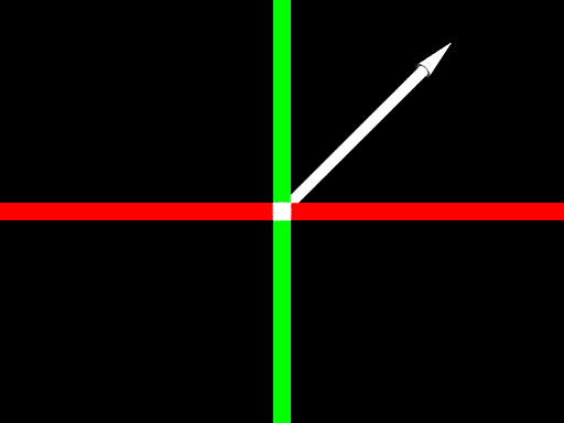
The vector on the (x, y) plane
Right below is the same scene from another viewpoint. The light is now shining directly from above. That is, the light is shining straight down parallel to the y-axis. Note the shadow of the vector on the x-axis. This shadow represents the x-component of the force vector.
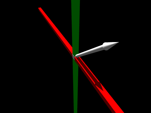
The x-component
Next, below, we have the same situation except the direction of the light has changed. The light now is shining from the right, parallel to the x-axis. A shadow of the force vector can be seen on the y-axis. This shadow, mathematically, is the y-component of the force vector.
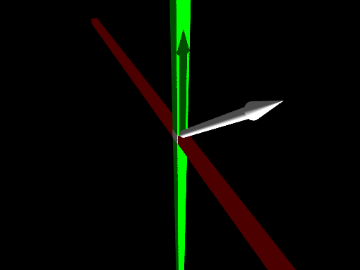
The y-component
Force vector component diagrams
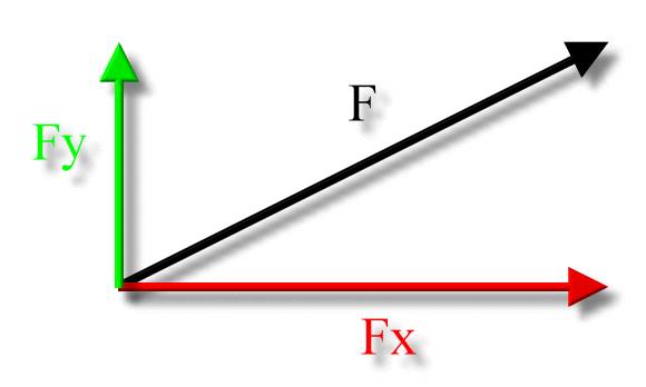
We are back to a flat surface diagram below; it shows how these components can be drawn.
The black vector is the two dimensional force vector, labeled F.
The red vector is the x-component of the force vector, labeled Fx. It would be pronounced 'F sub x'. Since 'x' is actually a subscript, this notation usually looks like this:
![]()
However, in Zona Land Education the subscript's position is often implied, as here, hopefully without any loss of meaning.
The green vector is the y-component of the force vector, labeled Fy, pronounced 'F sub y'.
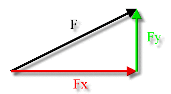
The components of the force vector can also be arranged this way, forming a right triangle:
Force vector component mathematics
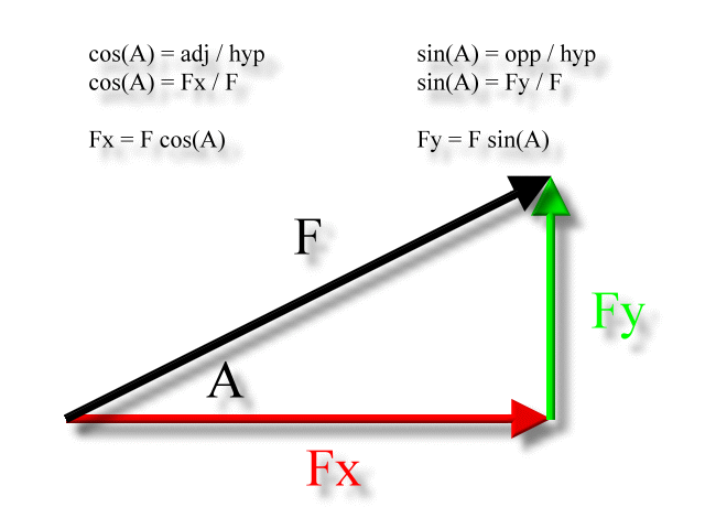
If we know the size of the two dimensional force vector, the black one in the above diagram, and the angle it makes with the x-axis, then we can use right triangle trigonometry to find the values for the components.
In the following diagram 'A' is the angle that the two dimensional force vector makes with the x-axis. Using right triangle trigonometry, Fx is adjacent to angle A, Fy is opposite to angle A, and F is the hypotenuse, as:
Unusual diagram
The above diagram shows how the trigonometry is usually presented - the cosine function is associated with the x-component and the sine function is associated with the y-component. However, it is not the only way to think about it. The following is a legitimate vector diagram for this force vector, but the x-component is calculated with the sine function, the y-component with the cosine. Note we are using angle B now; it's a different angle:
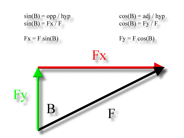
Remember, the diagram and formula derivation above, although correct within its own context, is unusual as far common textbook examples are concerned. They are usually set up to solve for the x-component using the cosine function and the y-component using the sine, as was presented originally with angle 'A'. There is good reason for this. If the direction of the force vector is given in standard position, as angle A could be interpreted, then the original derivations give correct results.
The sign of the components
The x-component of the force vector can be positive or negative.
- If it points to the right, it is positive.
- If it points to the left, it is negative.
The y-component of the force vector can be positive or negative.
- If it points up, it is positive.
- If it points down, it is negative.
When right triangle trigonometry is used, you need to consult your vector diagram to decide which way the components are pointing and then assign the correct sign to your calculated values as a last step in your solution. The right triangle trigonometry as presented here will always yield positive results. It is really only solving for the lengths of the legs of a right triangle, as one might do in Geometry studies.
Is F ever negative?
F, the value for the size of the two dimensional force vector, is always stated as a positive number.
Problem example
An object is pushed across a table top with a force of 16.6 N directed 32.7 degrees S of E. What are the x- and y-components of this force?
Here is the diagram:
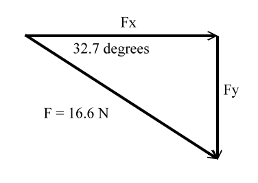
This is the solution:

Solving for the x-component, Fx:
|
|
Right triangle trigonometry: The cosine of an acute interior angle of a right triangle is equal to the length of the adjacent side to the angle divided by the length of the hypotenuse. |
|
|
Use the length of the force vectors as the lengths of the adjacent side and hypotenuse. Fx is the adjacent side, F is the hypotenuse. |
|
|
Algebra: Multiply both sides by F. |
|
|
Algebra: F's cancel on the right side. |
|
|
Algebra: Switch left and right sides. |
|
|
Plug in values. |
|
|
Cosine of 32.7 degrees is 0.8415. |
|
|
Multiply, result stated in significant figures. |
|
|
Final result stated with units. Note the positive value of the final result. It is positive because this is an x-component, and in the diagram it is aimed to the right. As usual with numbers, the plus sign is optional. |
Solving for the y-component, Fy:
|
|
Right triangle trigonometry: The sine of an acute interior angle of a right triangle is equal to the length of the opposite side to the angle divided by the length of the hypotenuse. |
|
|
Use the length of the force vectors as the lengths of the opposite side and hypotenuse. Fy is the opposite side, F is the hypotenuse. |
|
|
Algebra: Multiply both sides by F. |
|
|
Algebra: F's cancel on the right side. |
|
|
Algebra: Switch left and right sides. |
|
|
Plug in values. |
|
|
Sine of 32.7 degrees is 0.5402. |
|
|
Multiply, result stated in significant figures. |
|
|
Final result stated with units. Note the negative value of the final result. It is negative because this is an y-component, and in the diagram it is aimed down. |
Always remember to check back to the diagram to make sure you have the sign of the components correct.


